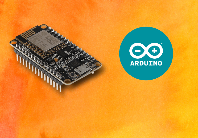
محیط آردوینو برای ESP8266

در این مقاله نحوه نصب ماژول ESP8266 را در محیط آردوینو در سیستم عامل ویندوز بررسی می شود.( در دیگر سیستم عامل ها، مشابه همین روش عمل می شود)
انجمن ESP8266 افزونه ای را برای Arduino IDE فراهم کرده است که به کاربران اجازه می دهد تا ماژول ESP8266 را با استفاده از محیط برنامه نویسی آردوینو کامپایل و برنامه ریزی کنید.
پیش نیاز: نصب محیط برنامه نویسی آردوینو Arduino IDE
قبل از شروع نصب، مطمئن شوید که آخرین نسخه Arduino IDE را در کامپیوتر تان نصب کرده اید. اگر این کار را نکردید، آن را حذف و دوباره نصب کنید. در غیر این صورت ممکن است درست عمل نکند. آخرین نسخه نرم افزار Arduino IDE در سایت شرکت آردوینو به آدرس زیر قابل دسترس می باشد:
https://www.arduino.cc/en/software
نصب افزونه ماژول ESP8266 در محیط آردوینو
برای نصب ESP8266 در Arduino IDE خود، مراحل زیر را دنبال کنید:
1. در Arduino IDE ، وارد گزینه File> Preferences شوید:

2. همانطور که در شکل زیر مشاهده می شود، مقدار زیر را
http://arduino.esp8266.com/stable/package_esp8266com_index.json
در قسمت Additional Boards Manager URLs وارد می کنید. سپس، روی دکمه “OK” کلیک کنید:

نکته: اگر از قبل URL ماژول ESP32 را دارید، می توانید URL ها را با ویرگولبه صورت زیر جدا کنید:
https://dl.espressif.com/dl/package_esp32_index.json, http://arduino.esp8266.com/stable/package_esp8266com_index.json
3. به منوی Tools رفته و سپس گزینه Board و در ادامه Boards Manager… را انتخاب کنید.

4. عبارت ESP8266 را جستجو کنید و سپس مشابه تصویر زیر، بر روی دکمه Install کلیک کنید.

5. پس از چند ثانیه افزونه ESP8266 نصب خواهد شد.

آزمایش نصب
جهت آزمایش نصب افزونه ESP8266، می توانید با استفاده از یکی از مثال های ESP8266 ، اقدام کنید:
برنامه LED چشمک زن
قطعات مورد نیاز
- ماژول ESP8266
- LED
- مقاومت 330 اهم
- برد برد (Bread Board)
- سیم های جامپر
برای راحتی آزمایش، پیشنهاد می شود از برد توسعه NodeMCU به جهت دارا بودن مدار برنامه ریزی داخلی استفاده کنید.
آپلود کردن برنامه
ابتدا مطمئن شوید که NodeMCU به سیستم متصل شده است. در ادامه از منوی Tools و سپس Board ، گزینه NodeMCU 1.0 را انتخاب کنید.

حال از منوی Tools و سپس Port ، پورت شناخته شده توسط سیستم را انتخاب کنید.

سپس کدهای زیر را داخل محیط ویرایش ، کپی کنید:
#include <ESP8266WiFi.h>#include "Adafruit_MQTT.h"#include "Adafruit_MQTT_Client.h"#include <ArduinoJson.h>#include <Wire.h>#include <OneWire.h>#include <DallasTemperature.h>//#include <Streaming.h>#include "SSD1306Wire.h" // legacy include: `#include "SSD1306.h"`#define ONE_WIRE_BUS 0 // DS18B20 pin GPIO10#define pin_buzzer D4#define pin_LED_red D7#define pin_LED_green D6#define pin_LED_blue D5#define pin_push_button D0#define pin_SCK D1#define pin_SDK D2int push_button=0;/************************* WiFi Access Point *********************************/#define WLAN_SSID "HeroLink"#define WLAN_PASS "HeroLink@123"/************************* Adafruit.io Setup *********************************/#define AIO_SERVER "broker.herolink.ir"#define AIO_SERVERPORT 1883 // use 8883 for SSL#define AIO_USERNAME "...your AIO username (see https://accounts.adafruit.com)..."#define AIO_KEY "...your AIO key..."/************ Global State (you don't need to change this!) ******************/// Create an ESP8266 WiFiClient class to connect to the MQTT server.WiFiClient client;// or... use WiFiFlientSecure for SSL//WiFiClientSecure client;// Setup the MQTT client class by passing in the WiFi client and MQTT server and login details.Adafruit_MQTT_Client mqtt(&client, AIO_SERVER, AIO_SERVERPORT, AIO_USERNAME, AIO_KEY);/****************************** Feeds ***************************************/// Setup a feed called 'potValue' for publishing.// Notice MQTT paths for AIO follow the form: <username>/feeds/<feedname>Adafruit_MQTT_Publish potValue = Adafruit_MQTT_Publish(&mqtt, "/feeds/potValue");Adafruit_MQTT_Publish robot_alive = Adafruit_MQTT_Publish(&mqtt, "/robot/alive");Adafruit_MQTT_Publish tempPublish = Adafruit_MQTT_Publish(&mqtt, "/temp");Adafruit_MQTT_Publish humdPublish = Adafruit_MQTT_Publish(&mqtt, "/humd");Adafruit_MQTT_Publish weatherPublish = Adafruit_MQTT_Publish(&mqtt, "/weather");// Setup a feed called 'ledBrightness' for subscribing to changes.Adafruit_MQTT_Subscribe ledBrightness = Adafruit_MQTT_Subscribe(&mqtt, "/feeds/ledBrightness");/*************************** Sketch Code ************************************/OneWire oneWire(ONE_WIRE_BUS);DallasTemperature DS18B20(&oneWire);// Initialize the OLED display using Wire library SSD1306Wire display(0x3c, pin_SDK, pin_SCK); //D2=SDK D1=SCK As per labeling on NodeMCU void setup() { Serial.begin(9600); delay(10); setup_LED(); setup_buzzer(); setup_LCD(); setup_WIFI(); setup_MQTT(); pinMode(pin_push_button, INPUT); // setup OneWire bus DS18B20.begin(); drawFontFaceDemo();}float getTemperature() { //Serial << "Requesting DS18B20 temperature..." << endl; float temp; do { DS18B20.requestTemperatures(); temp = DS18B20.getTempCByIndex(0); delay(100); } while (temp == 85.0 || temp == (-127.0)); return temp;}void loop() { // Ensure the connection to the MQTT server is alive (this will make the first // connection and automatically reconnect when disconnected). See the MQTT_connect // function definition further below. push_button = digitalRead(pin_push_button); Serial.println(push_button); if(push_button==1) { IntCallback(); } float humd=0.0;// = sht20.readHumidity(); // Read Humidity float temp=0.0;// = sht20.readTemperature(); // Read Temperature float temperature = getTemperature(); temp = temperature; Serial.print("Time:"); Serial.print(millis()); Serial.print(" Temperature:"); Serial.print(temp, 1); Serial.print("C"); Serial.print(" Humidity:"); Serial.print(humd, 1); Serial.print("%"); Serial.println(); DynamicJsonDocument doc(1024); doc["temp"] = temp; doc["humid"] = humd; char dataString[100]; serializeJson(doc, dataString); if (! weatherPublish.publish(dataString)) { Serial.println(F("Failed")); } else { Serial.println(F("OK!")); } delay(1000); displayWeather(temp,humd);/* drawFontFaceDemo(); delay(1000); drawRectDemo(); delay(1000); void drawCircleDemo(); delay(1000);*/ MQTT_connect(); // this is our 'wait for incoming subscription packets' busy subloop // try to spend your time here Adafruit_MQTT_Subscribe *subscription; while ((subscription = mqtt.readSubscription(200))) { //Serial.print(subscription); //ledBrightValue = atoi((char *)ledBrightness.lastread); //Serial.println(ledBrightValue); //Serial.println((char *)ledBrightness.lastread); //analogWrite(ledPin, ledBrightValue); /* if (subscription == &robot_move) { //move_stop(); //Serial.println((char *)robot_move.lastread); // char* tmp1 = strtok((char *)robot_move.lastread, "{"); // char* tmp2 = strtok((char *)tmp1[1], "}"); // Serial.println((char *)tmp2[0]); StaticJsonDocument<200> doc; DeserializationError error = deserializeJson(doc, (char *)robot_move.lastread); // Test if parsing succeeds. if (error) { Serial.print(F("deserializeJson() failed: ")); Serial.println(error.f_str()); return; } // x = doc["x"]; // y = doc["y"]; //Serial.println(x, 6); }*/ } // Now we can publish stuff! // uint16_t AdcValue = analogRead(A0); /*if((AdcValue > (potAdcValue + 7)) || (AdcValue < (potAdcValue - 7))){ potAdcValue = AdcValue; Serial.print(F("Sending pot val ")); Serial.print(potAdcValue); Serial.print("..."); if (! potValue.publish(potAdcValue)) { Serial.println(F("Failed")); } else { Serial.println(F("OK!")); } }*/ // ping the server to keep the mqtt connection alive // NOT required if you are publishing once every KEEPALIVE seconds /* if(! mqtt.ping()) { mqtt.disconnect(); } */}// Function to connect and reconnect as necessary to the MQTT server.// Should be called in the loop function and it will take care if connecting.void MQTT_connect() { int8_t ret; // Stop if already connected. if (mqtt.connected()) { return; } Serial.print("Connecting to MQTT... "); uint8_t retries = 3; while ((ret = mqtt.connect()) != 0) { // connect will return 0 for connected Serial.println(mqtt.connectErrorString(ret)); Serial.println("Retrying MQTT connection in 5 seconds..."); mqtt.disconnect(); delay(5000); // wait 5 seconds retries--; if (retries == 0) { // basically die and wait for WDT to reset me while (1); } } Serial.println("MQTT Connected!");}void displayWeather(float temp,float humid){ char temp_str[8]; // Buffer big enough for 7-character float char humid_str[8]; // Buffer big enough for 7-character float dtostrf(temp, 6, 2, temp_str); // Leave room for too large numbers! dtostrf(humid, 6, 2, humid_str); // Leave room for too large numbers! char temp_string[24]; strcpy(temp_string, "Temp: "); strcat(temp_string, temp_str); char humid_string[24]; strcpy(humid_string, "Humd: "); strcat(humid_string, humid_str); display.clear(); display.setTextAlignment(TEXT_ALIGN_LEFT); display.setFont(ArialMT_Plain_16); display.drawString(30, 0, "Herolink.ir"); display.setFont(ArialMT_Plain_16); display.drawString(0, 15, temp_string); display.setFont(ArialMT_Plain_16); display.drawString(0, 32, humid_string); display.display();}void drawFontFaceDemo() { // clear the display display.clear(); // Font Demo1 // create more fonts at http://oleddisplay.squix.ch/ display.setTextAlignment(TEXT_ALIGN_LEFT); display.setFont(ArialMT_Plain_10); display.drawString(0, 0, "Hello world"); display.setFont(ArialMT_Plain_16); display.drawString(0, 10, "Hello world"); display.setFont(ArialMT_Plain_24); display.drawString(0, 26, "Hello world"); // write the buffer to the display display.display();}void drawRectDemo() { // clear the display display.clear(); // Draw a pixel at given position for (int i = 0; i < 10; i++) { display.setPixel(i, i); display.setPixel(10 - i, i); } display.drawRect(12, 12, 20, 20); // Fill the rectangle display.fillRect(14, 14, 17, 17); // Draw a line horizontally display.drawHorizontalLine(0, 40, 20); // Draw a line horizontally display.drawVerticalLine(40, 0, 20); // write the buffer to the display display.display();}void drawCircleDemo() { // clear the display display.clear(); for (int i=1; i < 8; i++) { display.setColor(WHITE); display.drawCircle(32, 32, i*3); if (i % 2 == 0) { display.setColor(BLACK); } display.fillCircle(96, 32, 32 - i* 3); } // write the buffer to the display display.display();}void IntCallback(){ //Serial.print("Stamp(ms): "); //Serial.println(millis()); digitalWrite(pin_buzzer,LOW) ; //Turn on active buzzer delay (1000); digitalWrite(pin_buzzer,HIGH) ; //Turn on active buzzer delay (1000);}void setup_LED(){ for(int i=1;i<4;i++) { analogWrite(pin_LED_red,(i/1)*10); analogWrite(pin_LED_green,(i/2)*10); analogWrite(pin_LED_blue,(i/3)*10); delay(1000); } analogWrite(pin_LED_red,10); analogWrite(pin_LED_green,0); analogWrite(pin_LED_blue,0); }void setup_buzzer(){ pinMode (pin_buzzer,OUTPUT) ; for(int i=0;i<3;i++) { digitalWrite(pin_buzzer,LOW) ; //Turn on active buzzer delay (100); digitalWrite(pin_buzzer,HIGH) ; //Turn on active buzzer delay (100); }}void setup_LCD(){ display.init(); display.flipScreenVertically(); display.setFont(ArialMT_Plain_10);}void setup_WIFI(){ // Connect to WiFi access point. Serial.println(); Serial.print("Connecting to "); Serial.println(WLAN_SSID); WiFi.begin(WLAN_SSID, WLAN_PASS); while (WiFi.status() != WL_CONNECTED) { delay(500); Serial.print("."); } Serial.println(); Serial.println("WiFi connected"); Serial.println("IP address: "); Serial.println(WiFi.localIP()); change_status(1);}void setup_MQTT(){ void MQTT_connect(); // Setup MQTT subscription for ledBrightness feed. mqtt.subscribe(&ledBrightness); change_status(2);}void change_status(int status_){ switch(status_) { case 1://WIFI Connected analogWrite(pin_LED_red,0); analogWrite(pin_LED_green,0); analogWrite(pin_LED_blue,10); break; case 2://MQTT Connected analogWrite(pin_LED_red,0); analogWrite(pin_LED_green,10); analogWrite(pin_LED_blue,0); break; } digitalWrite(pin_buzzer,LOW) ; //Turn on active buzzer delay (100); digitalWrite(pin_buzzer,HIGH) ; //Turn on active buzzer delay (100);} |
روی آیکن آپلود کلیک کنید و چند ثانیه صبر کنید تا پیام “Done uploading.” درکادر پایین سمت چپ نمایش داده شود.

شماتیک مدار
همانطور که در شماتیک زیر مشاهده می شود، LED را به NodeMCU متصل شده است. LED باید به پایه GPIO 2 (D4) متصل شود.

اگر همه مراحل را به درستی پیش رفته اید، LED باید هر یک ثانیه چشمک بزند.


دیدگاهتان را بنویسید